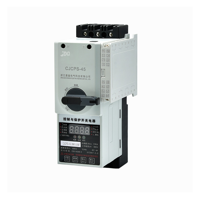
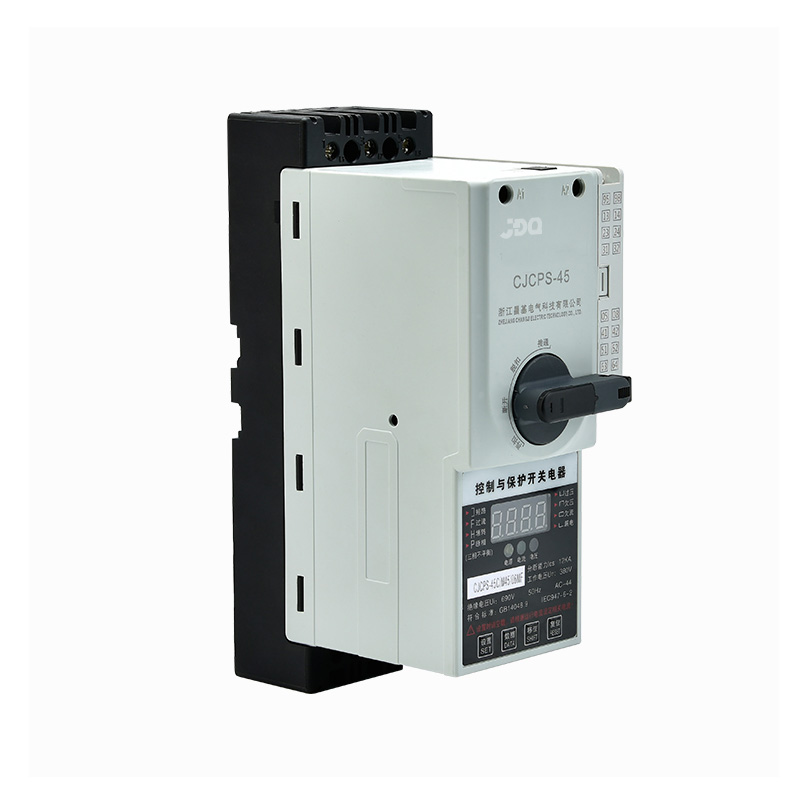


CPS adopts a modular single product structure type, which integrates the main functions of traditional circuit breakers (fuses, contactors, overload (or overvoltage, etc.) protection relays, starters, isolators, motor comprehensive protectors, etc. With remote automatic control and local direct human control functions, with panel indication and electromechanical signal alarm functions, with overvoltage and undervoltage protection functions, with phase failure and phase failure protection functions, small size, high reliability, and short circuit breaking capability High, short arcing distance and other advantages, with various characteristics, time-current protection characteristics with good internal coordination (inverse-time overload long-delay protection, short-circuit short-delay protection, time-limited short-circuit protection and fast instantaneous short-circuit protection, four-stage protection Features). According to the need to select functions or function modules, it can provide perfect control and protection functions for various power lines (such as frequent or infrequent starting of motors and distribution circuit loads), and the actions are accurate to avoid unnecessary power outages and improve power supply reliability.
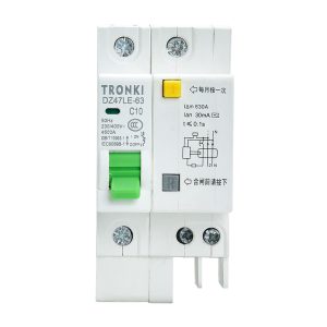
| Model Number: CPS-45 Pole: 1P/2P/3P/4P Breaking capacity: 4.5/6KA Rated voltage: 230/400V Rated current: 100A Standard: GB10963/IEC60898 | Product name: 63A Miniature Circuit Breaker MCB Frequency: AC 50/60 Hz Type: Mini Poles Number: Other Place of Origin: Zhejiang, China |
It is precisely because the CPS series products have superior performance and advantages, especially suitable for the following occasions synthesis system:
△ Power distribution and motor protection and control systems in metallurgy, coal mines, steel, petrochemicals, ports, ships, railways and other fields
△ Motor control center (MMC) and power distribution center;
△ Power station and substation;
△ Ports and railway systems (such as airports, railway and road passenger transportation centers, etc.);
△ Expressway lighting and ventilation systems;
△ Military station control and protection system (such as border posts, radar stations, etc.);
△ Fire pumps, fans, etc. in various occasions;
△Modern architectural lighting, power conversion, pumps, fans, air conditioners, fire protection, lighting and other electrical control and protection series;
△ Hospital;
△Commercial buildings (such as large shopping centers, supermarkets, etc.);
△Telecommunication room;
△Information processing center (such as municipal, bank, securities trading center, etc.)
△Single motor control and protection system in factory or workshop;
△ Remote control lighting system.
1.2 Use categories of products
The applicable use categories and codes of the main circuit and auxiliary circuit of the CPS are shown in Table 1
Table 1. Use categories to code names and typical uses of CPS products
| circuit | Use category code | Typical use |
| main battery | AC-20A | Closing and disconnecting appliances under no-load conditions |
| AC-40 | Power distribution circuits, including mixed resistive and inductive loads consisting of combined reactors | |
| AC-41 | Non-inductive or slightly inductive load, resistance furnace | |
| AC-42 | Slip ring type motor; start, clear | |
| AC-43 | Squirrel induction motor: starting, breaking during operation | |
| AC-44 | Squirrel induction motors: starting, braking in reverse or running in reverse, jogging | |
| AC-45a | Discharge lamp on and off | |
| AC-45b | On-off of incandescent lamps | |
| Auxiliary power | AC-15 | Controlling AC Electromagnetic Loads |
| AC-20A | Closing and disconnecting appliances with no-load spare parts | |
| AC-21A | On-off resistance to the load, including appropriate overloads | |
| DC-13 | Controlling DC electromagnet loads | |
| DC-20A | Closing and disconnecting appliances under no-load conditions | |
| DC-51A | Turns on and off resistive loads, including proper overshoot |
1.3 The product meets the standard
This product complies with IEC60947-6-2 “Low-voltage switchgear and control equipment – Part 6: Multifunctional electrical appliances, Section 2: Control and protection switching equipment” and GB14048.9 “Low-voltage switchgear and control equipment Multifunctional electrical appliances (equipment) No. Part 2: Standard for control and protection switchgear (equipment).
2.1 Ambient air temperature
2. 1. 1 The upper limit value does not exceed +40P;
2. 1.2 The lower limit is not lower than -5℃;
2. The average value of 1.3 days does not exceed +35℃,
2. 1.4 When the ambient air temperature exceeds the above range, the user can negotiate with our company.
2.2 The altitude of the installation site shall not exceed 2000 meters.
2.3 Atmospheric conditions
The relative humidity of the atmosphere does not exceed 50% when the ambient air temperature is +40°C: higher relative humidity can be obtained at lower temperatures. When the monthly average minimum temperature is +25°C, the average maximum relative temperature of the month is 90% due to Measures must be taken for condensation on the product due to temperature changes.
2.4 Pollution level: Level 3
2.5 Installation category: Class II (690V system), Class IV (380V system)
2.6 The control power supply voltage should be within the fluctuation range of (85%~110%) Us
三. Product model and meaning
| Model:CPS □-□/□/□ / □ □ | CPS | Control and protection switch appliances (multi-function appliances) |
| £ | Product combination type: basic type without code, N-reversible motor controller, J-decompression starter, S-double electric appliance, D-double-speed motor controller, Z-autocoupling decompression starter | |
| £ | Main body current: 6.3/12/16/18/32/45/63/100/125A | |
| £ | Breaking capacity (ICa): C-economical type 35KA, Y standard type 50KA H-high breaking type 60KA | |
| £ | Main circuit pole number code: 3, 4 | |
| £ | Intelligent release code: expressed by category code * rated current (B-basic type, E-advanced type) * (0.4-125A) | |
| £ | Auxiliary contact code: 02, 06 | |
| £ | Control power supply voltage (Us): M220V, 0~380V | |
| £ | Additional function code: reactance ~ no code, power distribution-P, fire-fighting-F, leakage-L, communication-T, isolation-G |
4.1 Parameters of the main circuit
The main circuit is mainly composed of the main body and the intelligent release, these two parts are the minimum configuration of the applicable CPS products.
The main body rated current In, the conventional heating current Ith, the rated insulation voltage Ui, the rated frequency, the rated working voltage Ue and the rated working current le range or control power range of the optional intelligent controller are shown in Table 2 and Table 3.
Ue and Keyi’s intelligent control device’s fixed working current to range or drag power range is shown in Figure 2 and Table 3. Table 2
The basic parameters of the circuit
| Inm | ln(A) | lth(A) | UI(V) | 额定频率(Hz) | Ue(V) |
| 45 | 3、6.3、12、16、32、45 | 45 | 690 | 50/60 | 360/690 |
| 125 | 12、16、18、32、45、63、100、125 | 125 |
Main parameters of the main circuit
| Frame current Inm | Intelligent controller rated current Ie | Long delay setting range Ir | Short time delay setting current Is | 380V control power (KW) | Main body rated current In | Use type | ||||
| 45 | 0.4 | 0.16~0.4 | 0.48~4.8 | 0.05~0.12 | ||||||
| 1 | 0.4~1 | 1.2~12 | 0.12~0.33 | |||||||
| 2.5 | 1~2.5 | 3~30 | 0.33~1 | |||||||
| 4 | 1.6~4 | 4.6~4.8 | 0.53~1.6 | 12 | ||||||
| 6.3 | 2.5~6.3 | 7.5~75.6 | 1~2.5 | |||||||
| 10 | 4~10 | 12~120 | 1.6~5.5 | 16 | ||||||
| 12 | 4.8~12 | 14.4~144 | 2.2~5.5 | |||||||
| 16 | 6.4~16 | 19.2~192 | 2.5~7.5 | 18 | ||||||
| 18 | 7.2~18 | 21.6~216 | 3.3~7.5 | |||||||
| 25 | 10~25 | 30~300 | 5.5~11 | 32 | ||||||
| 32 | 12.8~32 | 38.4~384 | 5.5~15 | |||||||
| 40 | 16~40 | 48~480 | 7.5~18.5 | 45 | ||||||
| 45 | 18~45 | 54~540 | 7.5~22 | |||||||
| 125 | 6.3 | 2.5~6.3 | 7.5~75.6 | 1~2.5 | ||||||
| 10 | 4~10 | 12~120 | 1.6~5.5 | 12 | ||||||
| 12 | 4.8~12 | 14.4~144 | 2.2~5.5 | 16 | ||||||
| 16 | 6.4~16 | 19.2~192 | 2.5~7.5 | 18 | ||||||
| 18 | 7.2~18 | 21.6~216 | 3.3~7.5 | 32 | ||||||
| 25 | 10~25 | 30~300 | 5.5~11 | |||||||
| 32 | 12.8~32 | 38.4~384 | 5.5~15 | 45 | ||||||
| 40 | 16~40 | 48~480 | 7.5~18.5 | |||||||
| 45 | 18~45 | 54~540 | 7.5~22 | 63 | ||||||
| 50 | 20~50 | 60~600 | 7.5~22 | |||||||
| 63 | 25.2~63 | 75.6~756 | 11~30 | 100 | ||||||
| 80 | 32~80 | 96~960 | 15~37 | |||||||
| 100 | 40~100 | 120~1200 | 18.5~45 | 125 | ||||||
| 125 | 50*125 | 150~1500 | 22~55 | |||||||
Note:
※The parameter of instantaneous protection is not adjustable, its value is rated at 16Ir
※The adjustable range of the short-time delay protection setting parameter Is for motor products is 6Ir-12Ir
※The adjustable range of the short-time delay protection setting parameter Is of power distribution products is 3Ir-6Ir
※The above power range refers to the technical parameters of Y series three-phase asynchronous motors
※If you have special requirements, please contact the manufacturer
4.2 CPS protection characteristic curve
CPS Motor Protection Time-Current Characteristics CPS power distribution protection time-current characteristics
4.3 Action characteristics for motor control (applicable categories: AC-42, AC-43, AC-44)
| serial number | Multiples of setting current (Ir1) | When and when the agreement related to Ie | Reference temperature |
| 1 | 1.0 | 2h Does not trip | +40℃ |
| 2 | 1.2 | 2h Internal trip | |
| 3 | 1.5 | 4min Internal trip | |
| 4 | 7.2 | 4-10s Internal trip |
4.4 Action characteristics for distribution line load (use category: AC-40, AC-41)
| Applicable category | Multiples of setting current (Irl) | Appointment time in relation to Le | Reference temperature | ||
| A | B | le<63A | Le≥63A | ||
| AC-40、AC-41 | 1.05 | 1.3 | 1 | 2 | +30 C |
| Note: A is the agreed non-action current, B is the agreed action | |||||
4.5 Main technical parameters of intelligent release
4.5.1 Start Delay
During the CPS start-up time, it only protects the lack of fuse, phase failure, overvoltage, undervoltage, undercurrent, short circuit, leakage and three-phase unbalance. To avoid the protection of high current and overcurrent when the CPS starts; the setting time is ( Choose between 1~99) seconds;
4.5.2 Overvoltage and undervoltage protection
Only the auxiliary supply voltage is protected to ensure proper coil operation.
Overvoltage protection: When the auxiliary power supply voltage exceeds the set value (factory setting is 120%Us), the action time is less than or equal to 10 seconds
Undervoltage protection: when the auxiliary power supply voltage is lower than the set value (factory setting is 75%Us), the action time is less than or equal to 10 seconds
4.5.3 Inverse-time-load long-delay protection
The user sets the rated working current le of the intelligent release according to the load current I, so that the load current I is between 80 and 100% le, and the action time is set according to the load characteristics. See Table 4 for the characteristics of overcurrent multiples and action time. Time limit overload long delay protection characteristic curve is factory set at F2
Table 4. Action characteristics of CPS inverse-time overload long-time protection
| Overcurrent times | time(S) | serial number(F) | 1 | 2 | 3 | 4 |
| l.0 | no action | no action | no action | no action | ||
| ≥1.1 | 5 | 60 | 180 | 600 | ||
| ≥1.2 | 5 | 50 | 150 | 450 | ||
| ≥1.3 | 5 | 35 | 100 | 300 | ||
| ≥1.5 | 5 | 10 | 30 | 90 | ||
| ≥2.0 | 5 | 5 | 15 | 45 | ||
| ≥3.0 | 5 | 2 | 6 | 18 | ||
4.5.4 Undercurrent Protection
Undercurrent protection: It is based on the ratio of the minimum current to the rated current to determine whether to activate the undercurrent protection (the factory setting is 60%). The working current le of the CPS intelligent release, so that the motor is not within the protection range of the CPS.
When the current is less than the set value of the undercurrent protection, the action time is less than or equal to 30 seconds.
4.5.5 Three-phase unbalanced (broken, missing phase) protection
Three-phase unbalance protection is based on the ratio of the difference between the maximum and minimum current to the maximum current to determine whether to start the three-phase unbalance (break, phase loss) protection
(Unsettling rate = (maximum current – minimum current>/maximum current)
When the difference of any two-phase current value exceeds 20~75% (the factory setting is 60%), the action setting time is less than or equal to 3 seconds.
4.5.6 Stall protection
Locked-rotor protection is to prevent the motor from heating and damaging the motor due to serious operation blockage of the driving equipment or overloaded operation of the motor. Generally, the working current reaches the set value to judge whether to activate the locked-rotor protection.
When the working current reaches 3.5~8 times of the rated current, the action time is less than or equal to 0.5 seconds.
4.5.7 Short circuit short delay protection
When the working current reaches more than 8 times of the rated current, the action time is less than or equal to 0.2 seconds.
4.6 Ability to make, carry and break short-circuit current
| Ue (V) | main body current In(A) | Rated operating short-circuit segment capacity los(kA) | Expected contract test electric value lcr(A) | Additional segmentation capabilities lc(A) | ||
| S type | N type | H type | ||||
| 380 | 12、16、18、32、45、63、100、125 | 35 | 50 | 80 | 20×100 (which is2000) | 16x100x0.8 (which is1280) |
| 690 | 10 | 10 | 10 | |||
4.7 Main circuit electrical life times and making and breaking conditions
| Ue(V) | use category | Electrical life | On condition | Division condition | |||||
| new test | After rated operation short-circuit test | Expected Conventional Current After Test | l/le | U/Ue | lc/le | Ur/Ue | cosφ | ||
| 380 | AC-43 | 100×104 | 1.5×10³ | 3×10³ | 6 | 1 | 1 | 0.17 | 0.35 |
| AC-44 | 2×10⁴ | 6 | 1 | ||||||
| 690 | AC-44 | 1×10⁴ | |||||||
| Frame class code and module name | Mechanical life |
| main body | 500×104 |
| auxiliary contact | |
| Signal alarm auxiliary contact | 1×10⁴ |
| Operating mechanism |
4.8 Mechanical life of the main body and its modules
5.1 Panel Display and Key Instructions
Before the CPS is energized and closed, the long-delay and short-delay setting currents should be set to the required values according to the line load current it controls and protects. After the power is turned on, the digital tube lights up, displays the auxiliary current and voltage value, and cyclically displays the monitored operating current value of the A, B, and C three-phase circuits.
5.2 Running operations
Setting key: When the load is not running, press this key to enter the state of parameter setting
Shift key: Select the set word bit in the setting state, and the selected word bit is in the blinking state
Data key: Modify the flashing word bit. The level difference is 1 {0 to 9 cycles}
Reset key: After the parameter setting is completed, press this key to save the parameter and put it into the normal monitoring operation state
5.5.1 After the CPS is connected to the working power supply, the LED displays the voltage value, which can also be used as a voltmeter, and the last three digits display the voltage value.
5.5.2 The CPS can also be used as an ammeter during operation to display the three-phase current operation in a cycle.
Press the “shift key” to directionally display the current extension status of A-phase, B-phase, C-phase and L (leakage).
Press the “reset key” to resume the cycle display of the three-phase current operation.
5.2.3 Troubleshooting
No-load operation of CPS, press the “data key”, compare with the fault type symbol on the panel, you can check the first three fault types; when the voltage value is displayed, it means
The CPS has exited the fault query and is put into normal monitoring operation status: or restart the CPS to exit the fault query
5.3 Protection parameter settings
When the motor starts and runs, pressing the setting key is invalid;
No-load running cps: press “set key” to select setting type, press “shift key” in turn, select data shift, press “data key” to modify data;
After a parameter is set, press the “set key” again to enter the next setting state, until the end;
Unneeded selection should abandon the setting. After all parameters are set, press the reset key to exit the setting state and display the voltage value.
[Sassy_Social_Share]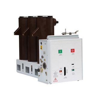
tel
+86-15869671247